After having read what options are available and people saying that some of those wired scene controllers are not easy to setup… I thought that this could not be rocket science but I was wrong.
I spent one whole morning with reading, research, verbose logging, try and error to finally get this working and before somebody else faces the same dilemma I am going to share on how to get this going. If this is the best approach… I don’t know but it meets my requirements now.
Setup:
– Philips Hue Lights with ethernet attached light hub controller
– Vera Light with Philips Hue Plugin installed
– working scenes applied to lights (5 scenes)
Goal:
– Not having to use the Vera GUI
– Not having to use the cell phone
– Use a wired Scene Controller to enable those 5 scenes
Steps to start ingration:
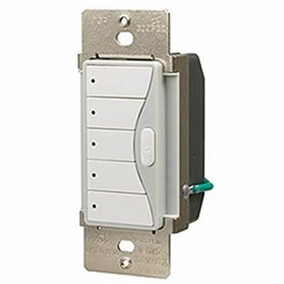
1) provide power to Cooper controller
2) Pair controller with Vera (procedure is documented in many places)
3) Scene Controller will show up in Vera as “Scene Contr”
First dilemma:
1) The settings of this scene controller are not intuitive and very misleading
2) This was never designed to trigger Vera scenes as it was designed to communicate directly with other Z-wave devices
3) You will not find any place where you can define the buttons of the controller and/or which scene to trigger
4) You will NOT be able to select the Scene Controller for any scene creation when you define what your scenes should do (red x)
5) Whatever you do, you will not see any scene data/information in your scene controller settings (Control, Advanced or Scenes) until you created what is described below and after that you will only see your scenes under Control and under Advanced in the line scenes but you will see nothing under the tab Scenes.
Logic to get this working:
1) You have to understand that you have to define your scenes first without any involvement of this scene controller
2) Those scenes should be able to run without any settings or integration of the scene controller and you should check them via your Vera GUI if those scenes do what they are supposed to do BEFORE you start messing around with the scene controller
3) Once if you have your scenes working you have to add triggers to those scenes which means your scene controller complements your scenes by acting as a trigger and not via the settings of the device in your Vera GUI
Programming the scene controller:
1) Pick your first scene in my case “Lights Relaxed” (this scene should already exist and should be working) and then click on triggers and add a new trigger.
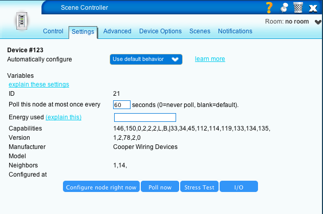
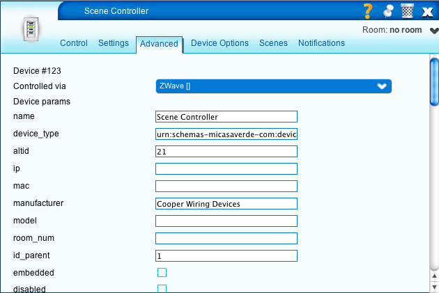
2) Select the scene controller (in my case ID123 see screenshots below with settings and trigger)
3) Select “A scene is activated” and this is the ONLY option you will need for any scenario
4) Give it any name you want
5) Where is says “Scene” you have to enter a number between 1 to 5 which represents the buttons on the Scene controller in my case 1 (see screenshot)
Repeat those steps for all 5 scenes until you have all buttons assigned.
Here comes another tricky part now…
Powering off lights failures:
1) There is the “All off” button on the scene controller and I could not get this to work despite all the workarounds I could research on the web and in this forum but I found a different way to address this
2) If you don’t have a way to power off the lights, any button you press wills start the scene and the scene will stay on and the blue LED on the scene controller will go on and off as you press the button but nothing will change
3) You can even press the different buttons on the scene controller and change between scene but assigning a scene where you power off the lights will not work. This is extremely frustrating.
Working solution:
1) You create a new scene which is “All Lights OFF” and you test this scene BEFORE you integrate the scene controller
2) Once you have your scene, edit the scene and do the exact same procedure as above where you assign a button to it but instead of picking a number between 1 and 5, you assign the number “0” and counter intuitive you have to select again “When a scene gets activated” instead of what logically would be “When a scene gets deactivated”.
Result:
1) When you press button 1, Lights relaxed scene gets executed, the blue LED goes ON
2) When you press button 1 again, Lights OFF will get executed, the blue LED goes OFF
3) When you press button 1, Lights relaxed scene gets executed, then you press button 2, Lights Night gets executed and you will see 2 blue LEDs ON but as soon as you press one of the two executed buttons/scene, the Lights OFF scene gets executed
4) I don’t need the “All OFF” button at all and it doesn’t even do anything
Additional troubleshooting note:
For whatever reason sometimes when you do all this trigger creation stuff and you don’t save after every step, you might end up with some of the buttons not working as they should despite all the settings showing up correctly. I had this twice. When this happens don’t try to modify around but go straight into the trigger section of your non-working scene controller button, remove the trigger and add a new trigger even if the settings you enter will be the exact same ones you can read on your screen. Sounds very weird but I had this 3 times until I get all my 5 buttons working as they should.
I hope this summary helps other people saving hours of time trying to integrate the cooper wired scene controller into their Vera network.
Additional recommendation to plugin developers:
Cooper Industries released a very sophisticated document about their hardware and settings and conditions which should be a great foundation for a proper plugin for Vera because I am sure that my implementation is not how it should be done and it doesn’t even use all the features and functions that product could provide. Take a look here…
I wanted to share a quick tutorial on how to add Logitech Quickcam Pro 9000 via BlueIris and stream live to AuthomationHD.
Assuming you configured BlueIris to have a working cam and use JPEG streaming over port 5000 which you can check via http://YOURIP:5000/ it should come up with http://YOURIP:5000/jpegpull.htm. If you don’t have that don’t continue and read the manual on how to get your camera working properly.
Once you have the above here are the steps to stream to your cell phone:
Step 1:
Apps –> Develop Apps –> Create Device
Enter the Following Info:
Device Type: urn:schemas-upnp-org:device:DigitalSecurityCamera:1
Internal ID: (Blank)
Descrition: <DeviceName>
Upnp Device Filename: (Blank)
Upnp Implementation Filename: (Blank)
IP Address: <Device IP:Port> (Ex. 192.168.1.200:5000)
MAC: (Blank)
Room: <Select/Associate if you already have the room created>
Parent Device: (Blank)
Select “Create Device”, “Device Created” message should appear with new Device ID
Step 2:
Device should now show up in “Devices –> All” (It won’t show correctly with no Cam Icon but we will add the rest of the settings to fix this)
Next, find this manually added device in the room you added…. Click Settings (Wrench Icon) and update the following fields:
Settings Tab:
URL: /image/Cam1?time=now (the name of your cam is important which you have to define in BlueIris. I chose “Cam1” see screenshot)
Username: <username> (optional)
Password: <password> (optional)
IP Address: (Should already be auto-populated)
To make the CAM visible in AuthomationHD you have to click “PIN to dashboard”.
Close out of settings and then click “Save”
Enjoy!
For the record:
Logitech Quickcam PRO 9000 with firmware 2.90.9018
UI5 VeraLite
AuthomationHD 3.2.1.5 ALPHA
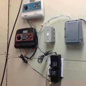
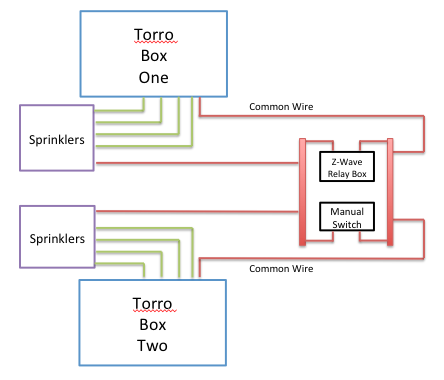
Wiring:
The Toro timers all connect to their corresponding sprinklers and each Toro has one “common” cable typically white connecting all sprinklers. I took the common cable from both Toros and connected them to the Terminal Ground Block.
A second Terminal Ground block is connected via the Z-wave relay and in addition to that I have a manual override switch installed because if something goes wrong with Vera or the Z-wave device malfunctions the sprinklers will not go on or off and they will just stay off.
Please understand that the Toros still have their standard water cycles and zones and times defined and they will always believe that they are doing their job. What I have done is to make them think they are doing their job but I control if they really water or not via Z-wave with Vera. The reason for the switch is because the Z-wave relay is always in an “OFF” state by default and if something goes wrong I am able to go there a use the override switch and the Toros will do their job as usual and the sprinklers will work. Kind of a failsafe if you wish as I don’t want to rewire the whole thing if something goes south.
Important note: You have to align the clocks of both Toros with your Vera clock or this whole thing will not work!!!
Logic programming:
I was thinking a lot about how to best utilize this setup and what use cases I want to cover and the only use case I came up for in my particular case is the bad weather condition where I want to be able to tell the system not to water but having been through this before where you walk to the Toros and you manually put them to “OFF” you have to remember to re-enable them again and the same applies here.
I wanted to make sure that if I say “don’t water” it should be only for one day and I don’t have to go back again. This “don’t water” action was also created as a scene in Vera which could then be triggered by the weather conditions of Wunderground.
There are other use cases where you want to control specific zones and you could code that by controlling the exact time with my proposed setup but I don’t need that.
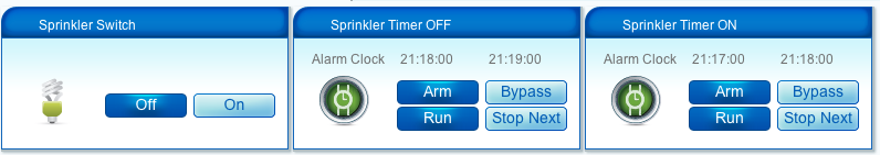
I have a total of 3 switches:
A) the Z-wave relay switch which I called “Sprinkler Switch”
B) Virtual Clock A which I called “Sprinkler Timer ON”
C) Virtual Clock B which I called “Sprinkler Timer OFF”
I have a total of 4 scenes:
1) “Sprinkler ON” which runs immediately and puts switch A above in the “ON” state
2) “Sprinkler OFF” which runs immediately and puts switch A above in the “OFF” state
3) “Stop next sprinkler cycle” which runs immediately and triggers “Stop Next” on switch B + triggers “Stop Next” on switch C above.3) “Stop next sprinkler cycle” which runs immediately and triggers “Stop Next” on switch B + triggers “Stop Next” on switch C above.
4) “Don’t water” scene (not shown)
Then I tested the scene “Stop next sprinkler Cycle” where if I run this scene the clocks B and C will simply not trigger their scenes for one time only. This means if tomorrow morning you see that it rains outside you can simply press the scene button and it will not trigger the sprinklers tomorrow night while this will only apply for tomorrow. The day after it will continue with the regular cycle.
In summary
I am now able to control my sprinklers centrally with all sprinklers on or off on a daily basis and if I do nothing they will do their daily job
I can now send a command to skip the next sprinkler cycle without having to worry about to re-enable the cycle again.
The Wunderground plugin of Vera provides weather information which can be used to trigger the fourth scene not to water if rain is in the forecast.
Futures:
I am attaching Wiring Diagram, screenshot of switches and scenes. If you guys see any flaw or logic or technical issues please let me know.
Hope you find all of this useful especially with only $106 bucks investment.