
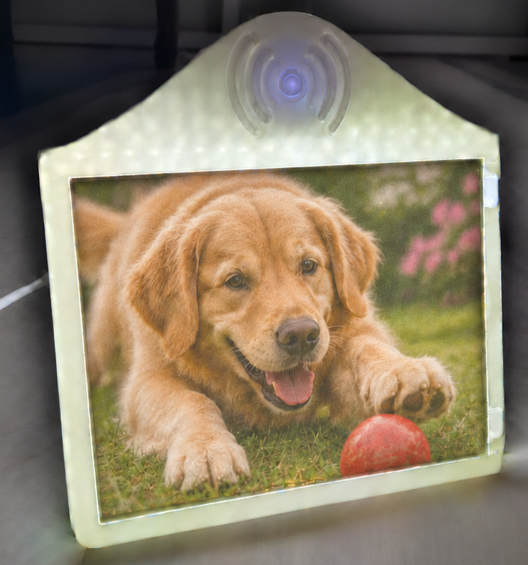
For all of the Lithophane enthusiasts out there, you might find this publication useful and worth your time. If you are familiar with Lithophane printing, then you have probably wondererd what the best way would be to control the light of that picture frame.
Instead of plugging and un-plugging the USB-C cable from the frame or using a USB-C adapter with a power on/off switch or even fancier using a smart plug you can control via voice or home assistant, you can now simply walk in front of it and even sit in front of it and it will stay lit until you walk away.
This publication is about using the official Bambu Labs Lithophane frame which you can get with any Lithophane picture you create under https://makerworld.com/en/makerlab/makeMyLithophane/ and the instead of using their official picture frame, you use this modified frame and a few electrical components.
There are 2 versions of this modification. One without soldering (it will not look as good and neat but fully functional) and a second version, which will require soldering of 5 cables and splicing a USB-C cable.
Let;’s start first with what a Lithophane is for people who don’t know. From Wikipedia:
“A lithophane is a thin plaque of translucent material, normally porcelain, which has been moulded to varying thickness, such that when lit from behind the different thicknesses show as different shades, forming an image. Only when lit from behind does the image display properly”
“Modern consumer 3D printing primarily employs two technologies for lithophanes: fused deposition modeling (FDM), which uses standard thermoplastic filaments like white polylactic acid (PLA) extruded layer-by-layer to control light transmission through varying thickness via multi-material 3D printing, which layers translucent cyan, magenta, yellow, and black (CMYK) plastics to mix colors when backlit.”
Next you will see an exampe of a Lithophane without light shining through and then with. Credits for those pictures go to:
By Elke Wetzig (Elya) – Own work, CC BY-SA 3.0, https://commons.wikimedia.org/w/index.php?curid=3280948


By Elke Wetzig (Elya) – Own work, CC BY-SA 3.0, https://commons.wikimedia.org/w/index.php?curid=3280948
As you can see, the picture without light is barely recognizable while the one with the light shining through becomes very recognizable.
Modern technology is allowing us now to print with our 3D Printers either black and white, gray shades or even color lithophane pictures.
This project can cover all of the above as it only helps you with the automatic light enablement behind that picture.
Each picture frame requires a LED matrix, which you can buy from various sources including Bambu Labs themselves for about $10 US dollars.
You can buy the same LED matrix boards from overseas but you need to make sure that the size and thickness matches and if they come in one piece or 2 pieces. Some of them come with an inline adapter to turn the light on or off and even adjust the brightness but it is all manual.
My first iteration of this was not adjusting the picture frame at all but instead using a C3 Super Mini ESP board with an LD2410c presence sensor and a USB3 Hub with on/off capability for power through mode.
In theory great, but it resulted in having to custom make a 3D printed case, which was not too bad, but then having to purchase a USB-splitter cable going from USB-A to USB-A and at the same time to USB-C (or use an adapter) and then going out again via USB-A to the USB-C power connector of the LED matrix of the Lithophane frame.
Then you have to position the sensor at the right angle somewhere else next to the frame or above or below it to be able to detect motion. Some might say that this is a benefit as you can decouple the sensor from the actual lithophane frame itself, but I can say that it was a cable disaster and unless you secure that case, it will move from all the cables being attached.
This is why I redesigned this from scratch and came up with a better solution embedding the sensor into the frame itself and only requiring one USB-C cable to power that whole solution as long as you can provide at least 2A or more, but more about this later.
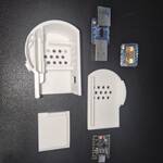
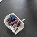
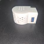
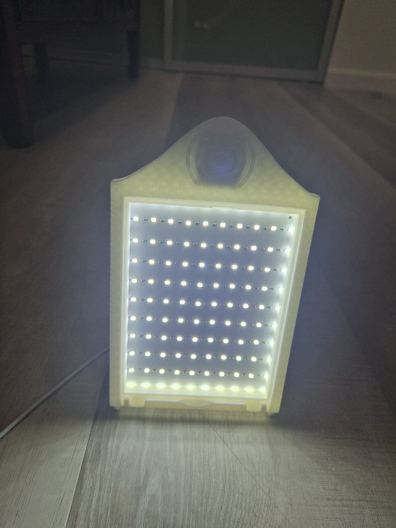
As mentioned earlier, you can download 2 versions of the frame. A portrait mode and a landscape mode frame and for both you can chose between plug&play or soldered version.
I am providing you the Fusion 360 (.f3d) files in case you want to modify the files and simply provide credit to my work when you publish a remix or a fork.
You will find the detailed components required below and a lot of testing has gone into this ranging from what ESP board to use, which provides 1A output to the LED matrix as normal ESP32 modules only provide 500mA output at 5V and can’t be switched hence picking up the a 3.3V presence sensor, but more about this later.
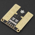
I researched almost all the presence sensors out there and I physically tested LC2410b, LD2140c, LD2410s, C4001 aka SEN0609 from Dfrobot, LD2420, LD2450, XIAO 101010001 and Waveshare S3KM1110.
Given that this picture frame is not about multi-person tracking and/or zones and simply to turn the light on/off for the frame the Dfrobot C4001 with 25 meters running at 3.3V is the best option.
Being able to use a single ESP32 board supplying 5V with 1A to the LED matrix and running a 24Ghz mmWave presence sensor at the same time has resulted in limiting my options to only the 3.3V presence sensors and continuously running without power fluctuations. At the time of this publication you can buy one of those sensors for $13.90 US dollars.
| Sensor | 3.3V supply | 5V supply |
|---|---|---|
| LD2410B | No | Yes |
| LD2410C | No | Yes |
| LD2410S | Yes | No |
| DFRobot C4001 / SEN0609 | Yes | Yes |
| LD2420 | Yes | No |
| LD2450 | No | Yes |
| Seeed mmWave for XIAO — 101010001 | Yes | No |
| Waveshare HMMD — S3KM1110 | Yes | No |
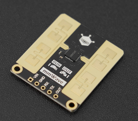
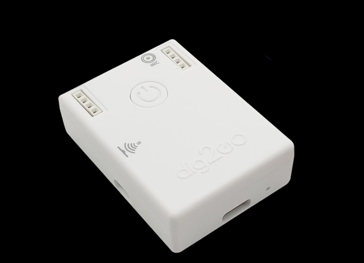
The other major component was to find an ESP board, which power the LED matrix and at the same time power the mmWave sensor reliably. I have all kind of ESP boards I have tested and used over time and I was not able to find one until I started thinking outside the box.
There is one product called Dig2Go, which you can find here https://quinled.info/quinled-dig2go/ which is usually used for very different use cases or applications mostly with wearables. Looking into the details of this solution, it has GPIO connections but also a 3.3V and a 5V power supply line. The bad news is because the 5V line is switched, turning off the matrix also turns off anything on that line, including the sensor.
As a result, only the 3.3V option remained hence the C4001 aka SEN0609 sensor being used here.
I would strongly recommend to purchase the D2G kit with the USB-Cable and the Power supply. This will save you a lot of headaches later.
You will require 2A to power this whole solution and this bundle comes with the USB cable and a 5V 3A power supply, which is more than enough for an additional $8.00 US dollars for both. Hard to beat that price. The complete bundle comes with the Dig2Go + USB cable + 3A power supply for $36.00 US dollars + shipping.
The other key part is the XH2.54 3Pin connector cable. This is usually attached to LED strips, but in this case to our LED matrix.
After relentless searching, there is no XH2.54 3Pin to USB-C on the market I could find. You can find XH2.54 4Pin and XH2.54 2Pin to USB-C cables, but not for XH2.54 3Pin.
This is where I mentioned before the USB-C cable splicing comes in. You have two options here. You either buy a terminal block USB-C cable and connect that to a XH2.54 3Pin female to XH2.54 3Pin male cable which has two additional wires sticking out for additional power injection, which is exactly what you can use to power the LED matrix. This is the path if you don’t want to or you don’t know how to solder and/or splice cables. It will not look as good, but it will be fully functional.
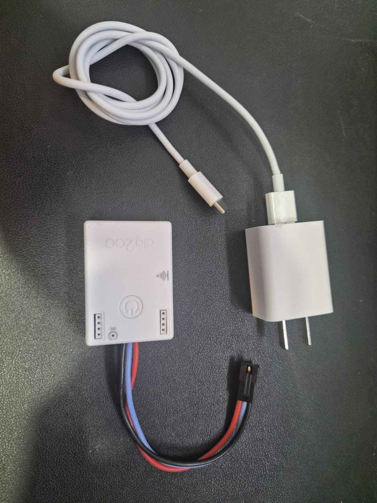
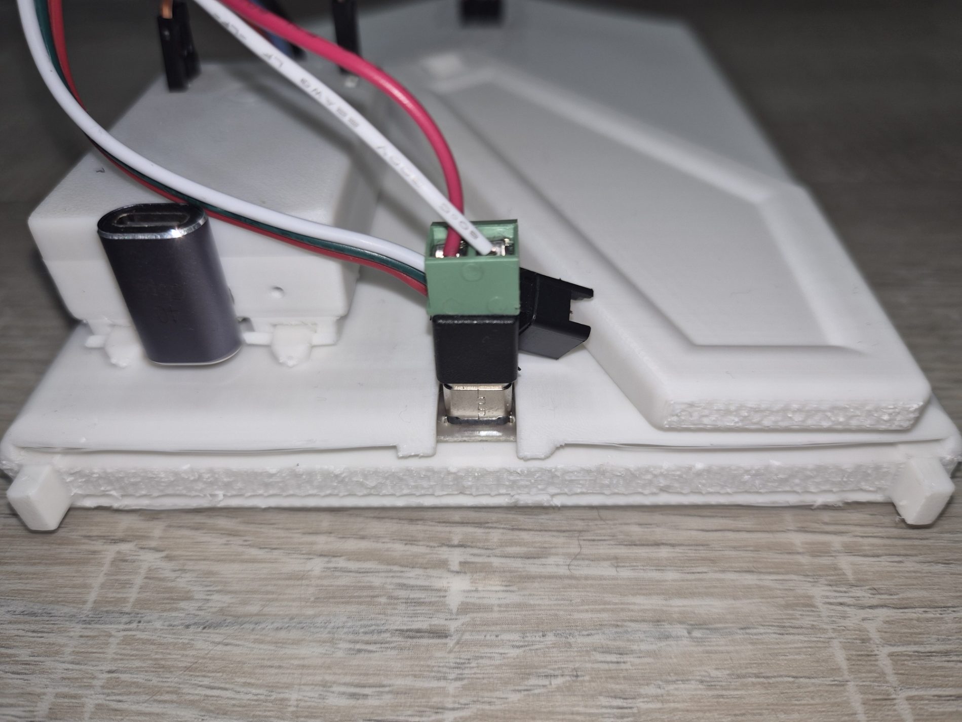
You can see in this picture the terminal block connected to the LED matrix and the 2 wires usually used for power injection into the LED strip to power the LED matrix.
This way you don’t have to cut any wires, solder anything or splice wires. Quick and easy hack.
You also can see on this picture a 90 degree angled USB-C connector to power the Dig2Go board. I would highly recommend that as most USB-C cable connectors are fairly long and it will lift your whole lithophane frame off the ground.
You could use a left or right angled USB-C cable connector, but this is really up to you, but I would refrain from using a right angled one as it might clash with your terminal block USB-C connector.
As I mentioned, this is the solder free version and you can see the complete solution on the right. You can see the USB-C terminal block connector, the Dig2Go with the 5 cables, which are dupont cables you can buy anywhere and you will need female to male cables to connect the Dig2Go to the C4001 sensor tucked away on top behind the sensor lid.
This is truly plug&play. The ONLY hard part for you will be to open the original Dig2Go case without breaking it in case you want to keep that case. I broke the fins of 2 of those cases trying to open them and each has 4 fins. They still work with 3 fins each.
Once you open the case, you have to decide if you want to use the plug&play method or if you want to make it really look neat and professional.
In case you want to make it look clean, then you will need to pull the 2 white blocks below carefully out. They should come off easily as long as you pull straight without bending while pulling.
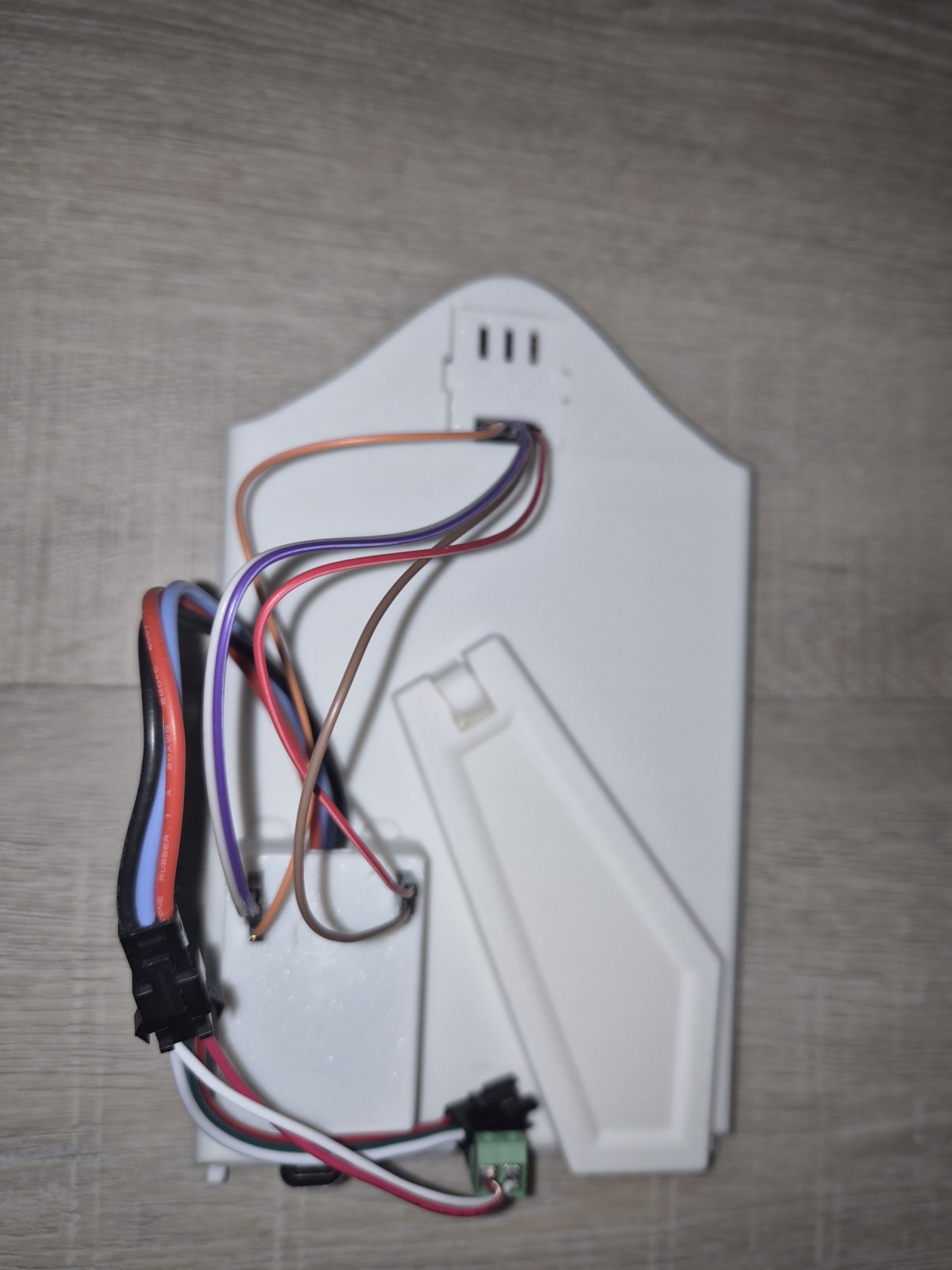
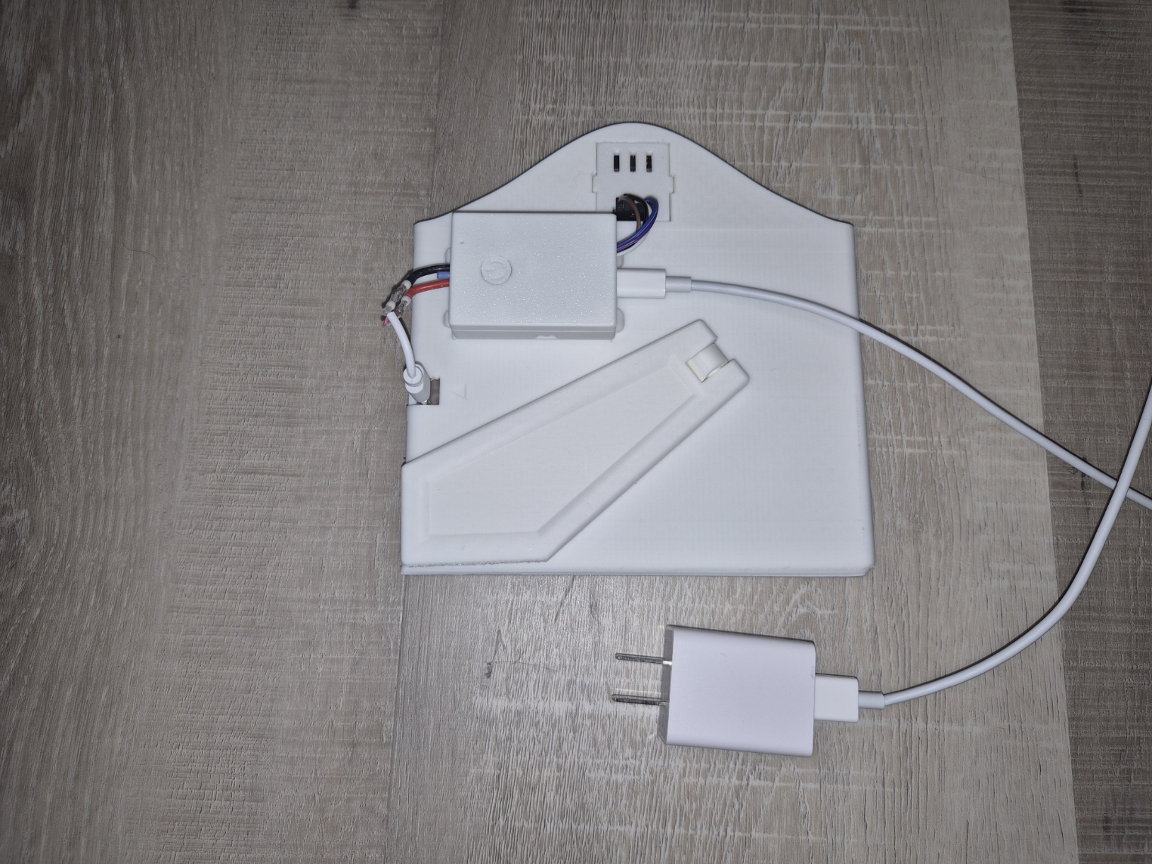
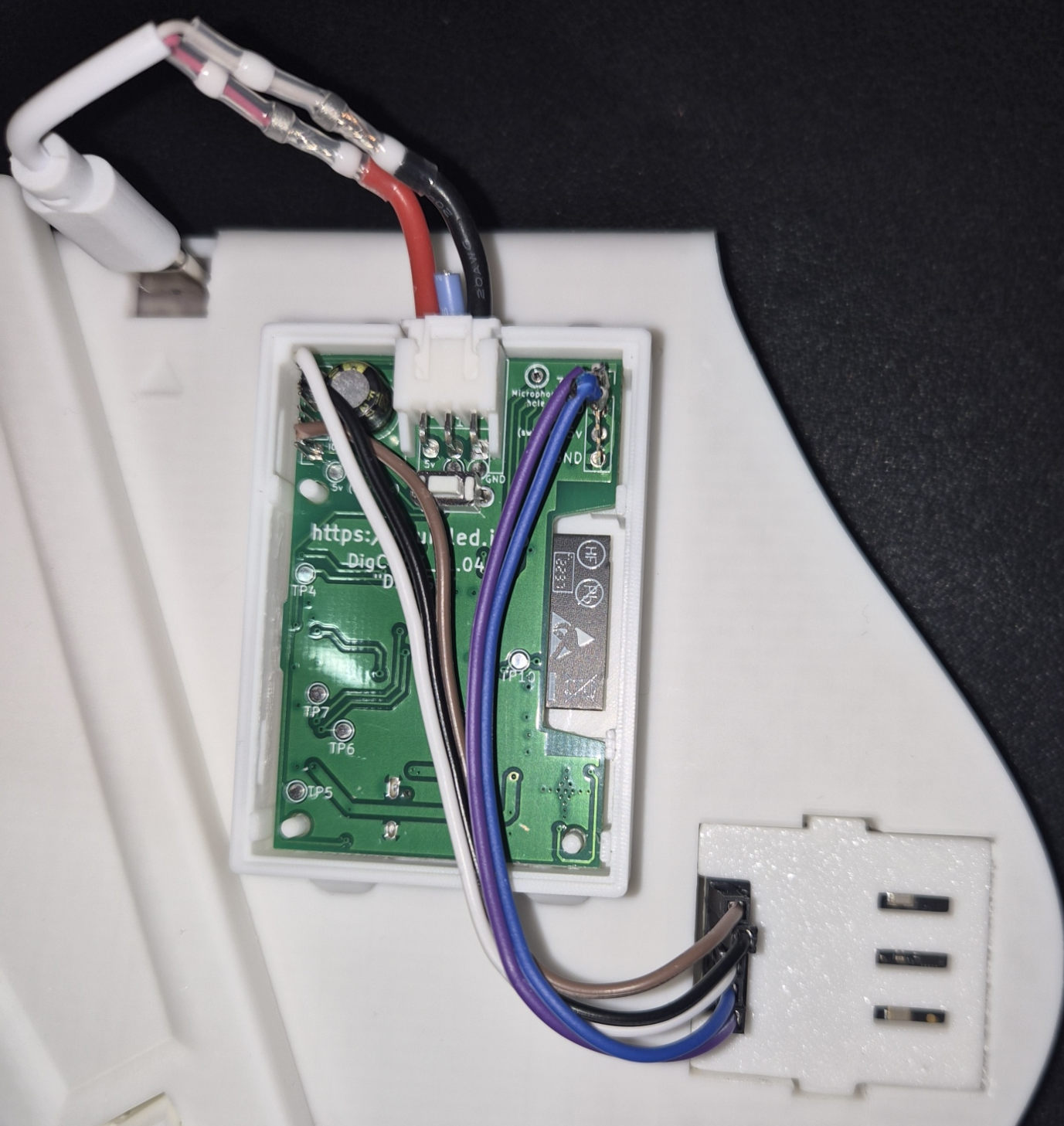
This picture shows you the soldered version and you will also notice that there are 2 STL files you can download. The portrait mode and landscape mode lithophane frame.
In this landscape version I connected 5 dupont cables to the C4001 sensor, which is simply push on but then I soldered the other side of each cable onto the metal clamps, which became visible pulling off the 2 white blocks shown earlier. Those Y shaped metal clamps are easier to solder on, but I do recommend to clip them a little bit as they are very long and with the wires, they might prevent your case from closing properly.
This also means, that you will find 2 STL files for the Dig2Go lid. One STL file without the 2 holes for the 2 white blocks and one version where those 2 blocks are closed and instead you have a side hole to route the wires out to the sensor.
You can see this additional hole in this picture allowing you to neatly route those 5 wires out to the sensor chamber.
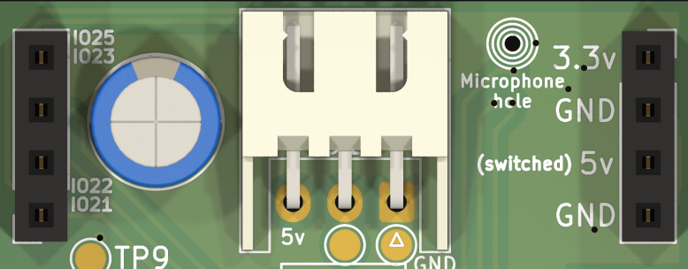
The pinout guide below shows you the GPIO headers on the left and the power and ground headers on the right.
In my picture the purple dupont cable is my 3.3V power going to the very right side of the C4001 (labeled VIN) and the blue wire going to the ground (second from top) to the second from the right on the C4001 (labeled GND).
The white wire on the top left labeled IO25 going to RX (middle connector on the C4001).
The black wire on the left (second from top) labeled IO23 going to TX on the C4001 (4th from the right).
The brown wire on the left (4th from the top) labeled IO21 going to the OUT on the C4001 (5th from the right or very first from the left).
The cover was designed after the original Dig2Go cover and that means that I kept the power on/off button on the case functional. As a result, you can simply push this button and the lithophane frame will simply stay off or if turned on, it will react to your presence.
You will also notice the USB-C cable connecting to the LED out port of the Dig2Go. This is where I used a simple cheap USB-C cable, cut it off and connected it to the cable, which came with the Dig2Go. I will wrap that with white tape later to make it really look nice. You can however, how the USB-C cable connects to the LED out port of the Dig2Go here.
The Dig2Go case is held in place using simple filament. You will find 2 holes in the two rail tracks, where you slide on the case. At the bottom of that track there is a hole on each side. Simply slide in filament to hold the case in place.
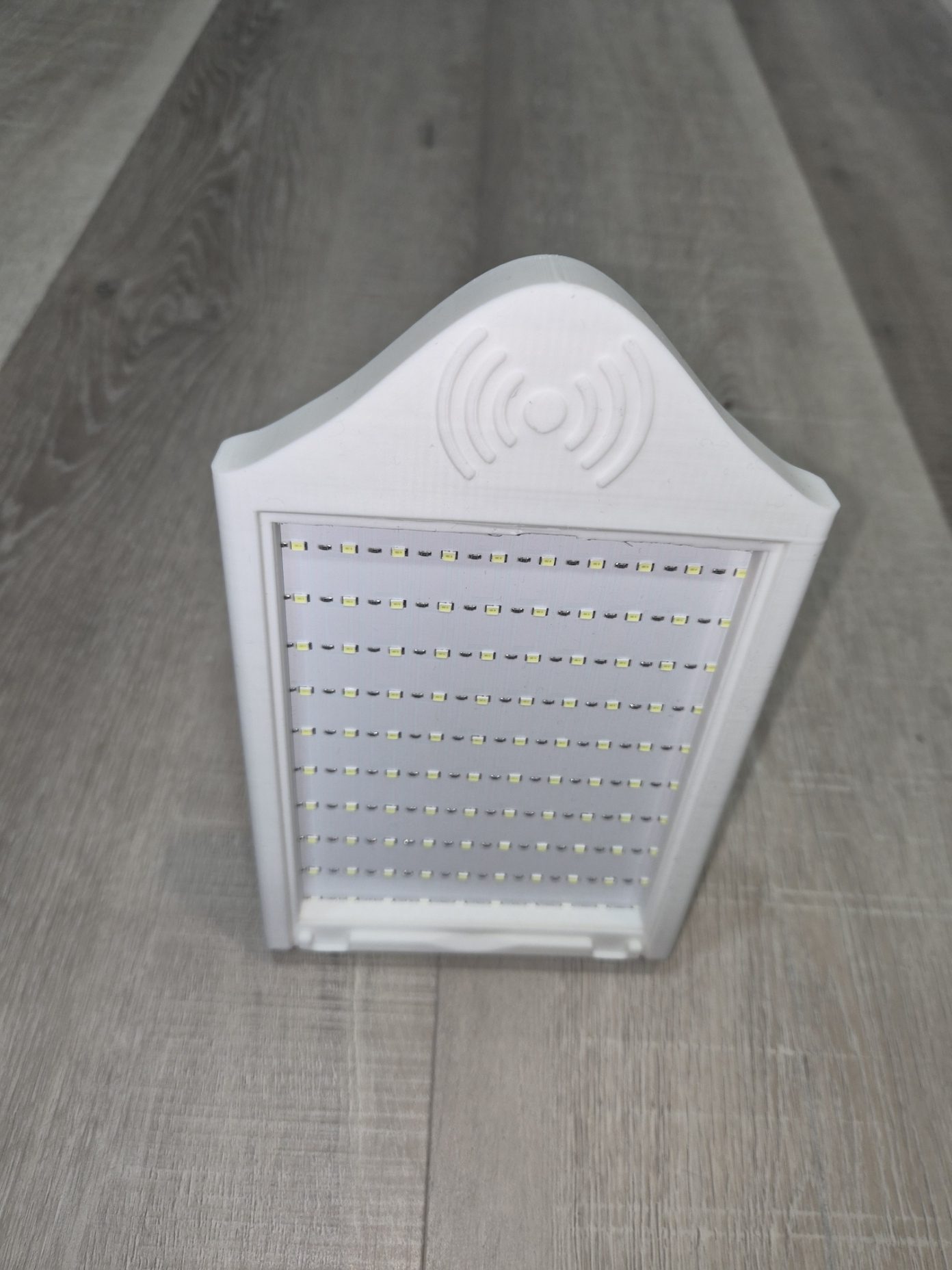
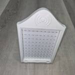
This is how it would look like with the LED matrix board inserted for a portrait mode lithophane frame.
The sensor is embedded right behind that motion sensor sign and if you print in white PLA, you will see a blue shimmer coming through from the C4001 when presence/motion detected and a green slow blinking light when no presence is detected. You can improve that if you change your 3D printer settings to use 100% infill for the presence sensor section.
If you don’t know how to do that, research for your 3D printer (Bambu, Snapmaker, etc) how to adjust infill for sections of your print. It is not difficult and studies have shown that using 100% infill for the wall in front of presence sensors actually increase the accuracy due to less bouncing of the radar signals.
Again, if you don’t like the look and feel and you want to change the sensor cap shape, feel free to use the Fusion 360 file and create your own sensor cap design, just reference my original design for your remix or forked design.
Before you ask the question, I did run a full 36h non-stop power-on test and I actually measured the temperature of the actually picture itself embedded in the frame and more importantly the actual C4001 sensor for various reasons.
1. to ensure the PLA does not warp or melt
2. The C4001 chamber has enough air flow without overheating (29C or 84F was the average temperature).
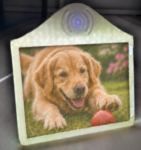
Here is the side by side view of the final portrait mode and landscape mode with 2 lithophane pictures and you will notice the blue shimmer of the sensor on top.
If you print in a darker PLA color and you go from the default of 15% infill to 100% infill for just that part in front of the sensor, that blue shimmer will no longer be visible.
Personally, I don’t care about that and it is good to see if the sensor is actually working or not. Your call.


Now, let’s talk about the software part as hardware and 3D printing is only half the story.
The Dig2Go comes pre-installed with the WLED software, which is great software but not useful for our use case.
You will have to visit https://web.esphome.io/ and connect your Dig2Go via USB-C cable to your computer (I used my Windows PC and I haven’t tried my Mac yet but they support both). Then you select your COM port and then you press on prepare for first use.
This will wipe the WLED software from the Dig2Go device and install ESPHome. From here you have 2 options.
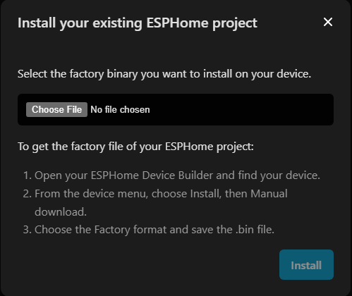
1. Non Home Assistant users: If you don’t have Home assistant installed, you can still proceed and use this https://homeautomation.expert/wp-content/uploads/2026/11/lithophane-frame-firmware.factory.zip file. You have to unzip the file and then use this file after you have prepared the Dig2Go for first use. The screen shows you when you click on install that you have to select a file to flash. Flash the .bin file from the extracted zip file. This will install ESPHome with the default settings on the Dig2Go.
2. Home Assistant users: After prepare for first use, you go into your Home Assistant and click on ESPHome Builder (install/enable if necessary) and then click on New Device, select or enter ESP32dev as the board and click create. Then click on edit and cut and paste the following YAML file stored in the ZIP file below. https://homeautomation.expert/wp-content/uploads/2026/11/lithophane-frame-public-yaml.zip
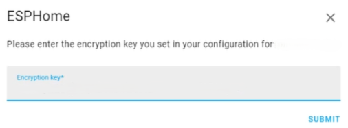
For Home assistant users: To remind you that all ESPHome devices require an API encryption key for security reasons. You need to copy that API key BEFORE you overwrite the YAML configuration. Store that key somewhere safe.
Then download the YAML file from here. https://homeautomation.expert/wp-content/uploads/2026/11/lithophane-frame-public-yaml.zip Download this zip file and extract the .yaml file. Cut and paste this YAML config into the device you just created.
Then copy back in the API key you saved away earlier. You will need this key after the reboot of the ESP device when you try to add this newly detected ESPHome device in your Home Assistant Settings – Devices. It will ask you for that key!
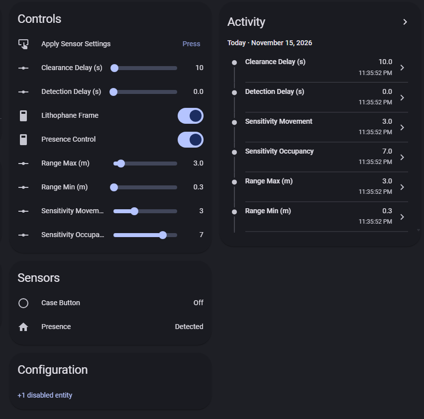
The controls in Home Assistant under ESP Home allow you to control settings like clearance delay, detection delay, frame on/off including presence control.
You can also adjust the sensitivity of the C4001 sensor based on your liking for motion and/or presence.
I should point out that the physical button on the Dig2Go itself acts as the general On/Off button for that Lithophane frame meaning if you turn it off, the frame will stay off regardless of any motion or presence detection.
I specifically left that button intact and compiled it into the code giving you physical control in case you want to manually turn off the frame and keep it off.
You can also schedule the On/Off with a Home assistant automation meaning that the frame will only turn on after sunset until sunrise or whatever schedule you chose. The possibilities are endless.
You could also use this sensor as a presence detector for your room and trigger other Home Assistant automations.
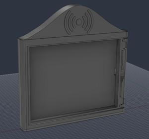
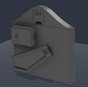
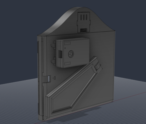
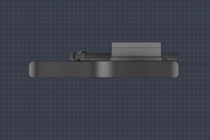
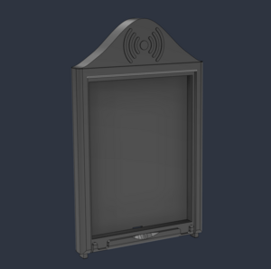
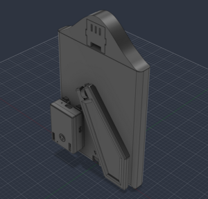
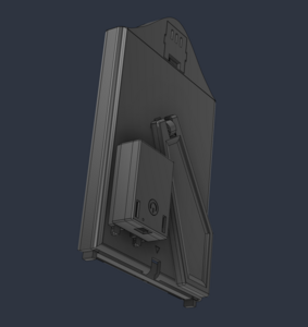
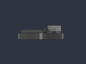

Landscape mode: Download the complete package of all STL files and the Fusion .f3d file and all screenshots compressed into this one zip File https://homeautomation.expert/wp-content/uploads/2026/11/Lithophane_Landscape_frame.zip

Portrait mode: Download the complete package of all STL files and the Fusion .f3d file and all screenshots compressed into this one zip File https://homeautomation.expert/wp-content/uploads/2026/11/Lithophane_portrait_frame.zip
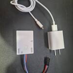
In summary you could create a presence sensing lithophane frame with your 3D printer and now you will ask, but what’s the cost:
1. Dig2Go + USB Cable + Power supply = $36.00 + shipping
2. C4001 aka SEN0609 sensor Dfrobot = $13.90 + shipping
3. LED matrix from Bambu labs shop = $9.99 + shipping
4. USB angled adapter optional = $2.90 + shipping
5. Dupont cables = $5.00 + shipping
6. Terminal block USB-C connector = $2.50 + shipping
7. LED female to LED male with power = $2.50 + shipping
* excluding PLA for printing your lithophane picture and also excluding the PLA to print your frame.
Total cost for neat & professional or plug&play will come to a total cost between $65.00 to $70.00 US dollars + shipping.*

