Select Page
Switchbot vision pro lock setup

Switchbot vision pro lock setup
Switchbot lock vision pro setup

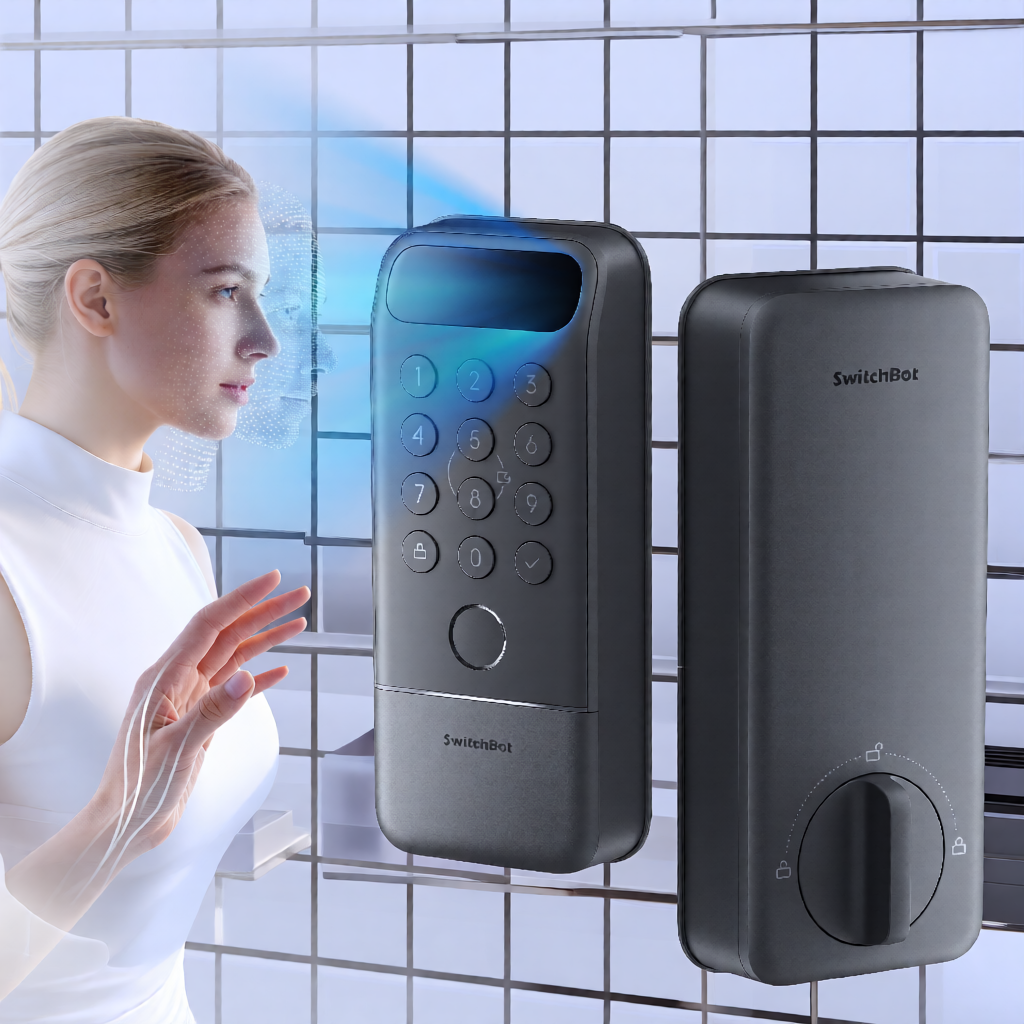
I recently installed the SwitchBot Lock Vision Pro at my home. As with any smart home addition, the goal was seamless integration into my existing ecosystem, specifically Home Assistant. The physical installation was straightforward, but the digital onboarding presented a specific hurdle that I want to detail here to save others the same confusion. This is not a review of the hardware’s features, but a report on the setup process, specifically the transition from a standalone device to a fully integrated Matter node.

Before diving into the steps, it is worth noting that I have covered various lock integrations in the past, such as my experience with the Yale door lock. Each manufacturer approaches connectivity differently, and SwitchBot’s approach via the app-first model has its own quirks. If you are following this guide, assume you have already purchased the device and completed the physical mounting. The focus here is the software handshake between the lock, your phone, and your hub.

Physical Fitment and Installation

The installation process began with the physical components. The Lock Vision Pro comes with several parts, including the main lock body, the keypad, and a specific plastic piece designed to interface with the outer door frame. This is where I encountered the only friction during the physical setup. The plastic piece that goes into the outer door frame was way too big to fit into the hole that was already there. It is a physical fit issue, not a manufacturing defect in the traditional sense, but a compatibility gap between the provided hardware and the existing door structure.

Once I resolved the fitment issue by adjusting the mounting point, the rest of the physical installation proceeded as expected. The alignment of the deadbolt mechanism and the keypad panel is standard. However, it is worth mentioning that if your door frame has a pre-existing cutout, you should measure the SwitchBot plastic insert before you start drilling or modifying the frame. I did not need to drill new holes, but the size mismatch required a different approach than the standard tutorial videos suggest.

Physical installation is only half the job. The lock is not smart until it is paired. I wanted to highlight this step because many users move straight to the app, assuming the physical mount guarantees functionality. In my case, the physical fit was the variable, not the procedure.

Initial Pairing via Bluetooth

After securing the lock to the door, I opened the SwitchBot app on my phone to initialize the device. The first step is always Bluetooth pairing. I held the pairing button on the lock until it entered discovery mode, then selected it in the app. This process is standard for most Bluetooth Low Energy (BLE) devices and did not present any issues. The connection was stable, and the app recognized the lock immediately.

At this stage, the lock is fully functional within the SwitchBot ecosystem. You can lock and unlock it, and trigger events. However, it is not yet integrated with other platforms. I have found that many users, including myself, overlook the next step.

My next step was to pair the lock with Home Assistant. I navigated to the Matter integration in Home Assistant and initiated the pairing process. I waited. Nothing happened. The lock was not showing up in the list of available Matter devices. I checked my Wi-Fi signal, my Matter bridge, and the lock’s power. Everything seemed correct, yet the device remained invisible to the hub.

I realized that I had assumed the lock was automatically broadcasting its Matter identity after the initial Bluetooth setup. This is a common misconception. Many manufacturers assume that once a device is set up in their app, it is discoverable by other platforms. In reality, the SwitchBot Lock Vision Pro requires you to explicitly enable pairing mode for Matter discovery from within the SwitchBot app. Nobody told me this. The onboarding guide in the app does not clearly state that you must return to the app to initiate this specific state before another platform can find the device.

I found this step online, in community forums and support documents that were not part of SwitchBot’s own onboarding flow. The solution was simple once I knew it existed. I had to open the SwitchBot app, navigate to the lock’s settings, and find the option to put the device into pairing mode for new controllers. This is distinct from the initial Bluetooth pairing mode. It is a specific state that tells the device, “I am ready to be discovered by a Matter controller.”

This is a critical detail. If you are following this guide, do not skip the Bluetooth setup. You must complete the initial configuration in the SwitchBot app. Then, to make it discoverable to Home Assistant (or any other Matter controller), you must go back into that same app and trigger the Matter pairing mode. The device acts as a Matter bridge, and the pairing mode allows the external hub to discover it on the local network.

Once I initiated this pairing mode from the SwitchBot app, I returned to Home Assistant and retried the discovery. This time, the lock appeared. The difference was not in my Home Assistant configuration, but in the state of the lock itself. It was waiting for a signal that it was authorized to be discovered by a new controller.

Switchbot lock vision pro setup

Joining via Matter over Wi-Fi

With the lock in pairing mode, I was able to use my cell phone and the Home Assistant companion app to join the lock to Home Assistant via the Matter over Wi-Fi protocol. The companion app is useful here because it allows you to manage the Matter pairing process directly from a mobile device, which can be more convenient if your main hub is running on a headless server or a device without a touchscreen.

The process of adding the device via Matter over Wi-Fi involved entering the Wi-Fi credentials for the lock. This is a crucial step. The lock needs to connect directly to your Wi-Fi network to function as a Matter node. It does not rely on the phone’s internet connection for this. You are essentially telling the lock, “Here are the network credentials, and here is the Matter commissioning payload. Connect and register.”

Once the lock connected to Wi-Fi and completed the Matter commissioning, it was visible in Home Assistant. The integration was clean. I could see the lock state, lock it, unlock it, and trigger events. The latency was comparable to other Wi-Fi-enabled devices, and the reliability has been consistent in my testing.

It is important to note that this setup allows the lock to be controlled locally through Home Assistant’s Matter integration. While the initial setup required the cloud (the SwitchBot app) to put the device in pairing mode, the ongoing operation is handled through the Matter protocol on your local network. This provides a level of privacy and speed that is often lacking in purely cloud-dependent devices.

Practical Insights and Next Steps

The key takeaway from this process is the importance of the “pairing mode” step in the SwitchBot app. If you find that Home Assistant cannot see your SwitchBot lock, this is the most likely culprit. The device is not broken, and your Matter configuration is likely correct. The lock is simply not broadcasting its presence to new controllers.

I have integrated other devices that require similar steps, such as the Z-Wave doorbell integration, where the pairing process is distinct from the initial setup. The principle is similar: the device must be in a specific state to be discovered. For the SwitchBot Lock Vision Pro, that state is managed within the proprietary app.

For those considering this lock for their own setup, I would recommend verifying that your Wi-Fi network is robust. Matter over Wi-Fi devices can be sensitive to signal strength. Since the lock is on a door, the distance to your router might be significant. I placed my router in a central location, but I would advise testing the signal strength at the door location before finalizing the installation.

In summary, the physical fitment of the outer frame piece was a minor hiccup, but the software setup required a specific, non-obvious step in the SwitchBot app to enable Matter discovery. Once that was done, the integration with Home Assistant via Matter over Wi-Fi was smooth. If you are looking for a lock that can fit into a modern, Matter-based smart home ecosystem, the SwitchBot Lock Vision Pro is a viable option, provided you are willing to navigate the initial app-based configuration. I hope this helps clarify the process. 
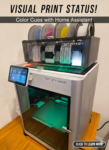
Visual Print Status – Color cues with Home Assistant

Visual Print Status – Color cues with Home Assistant

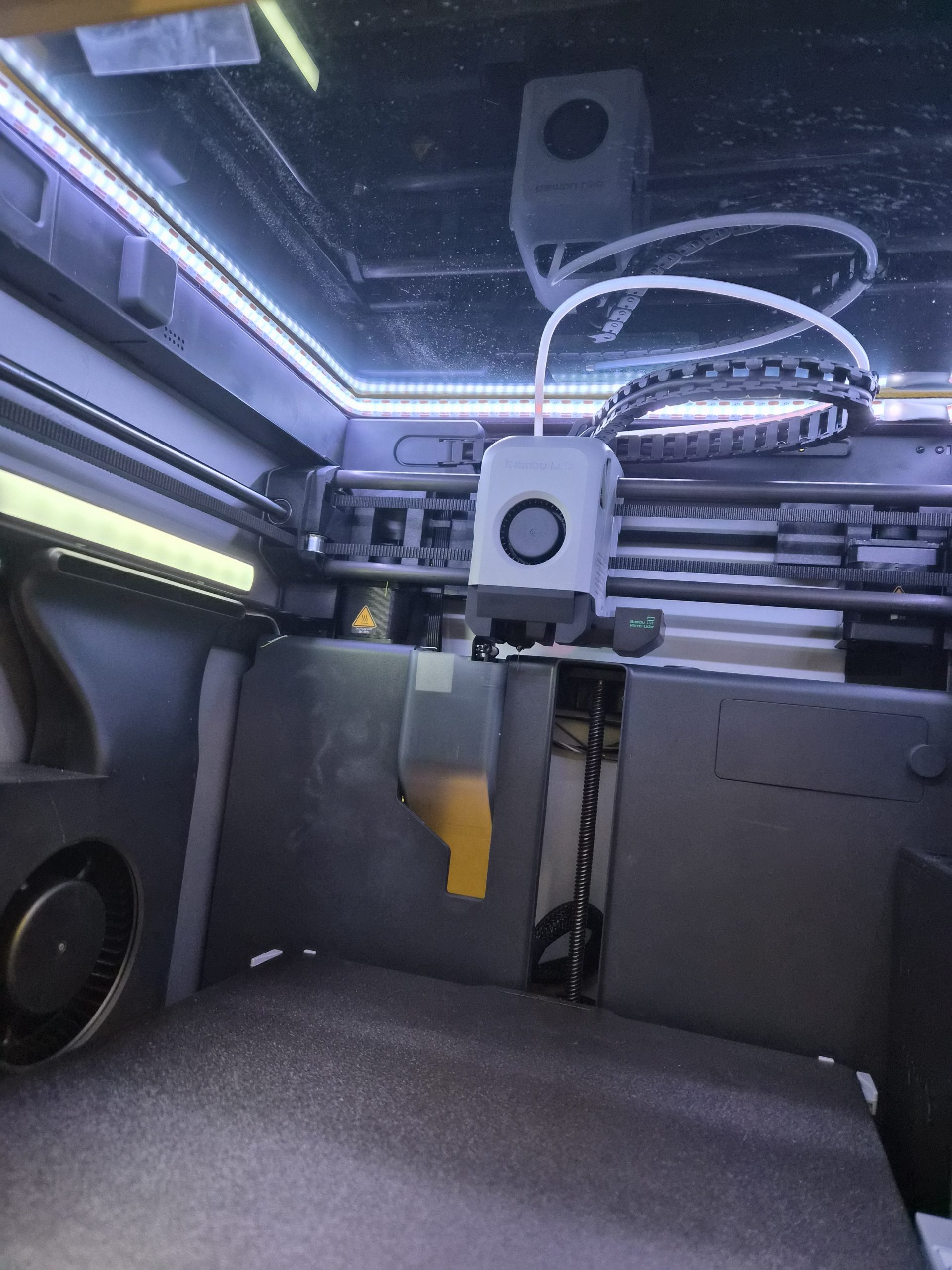
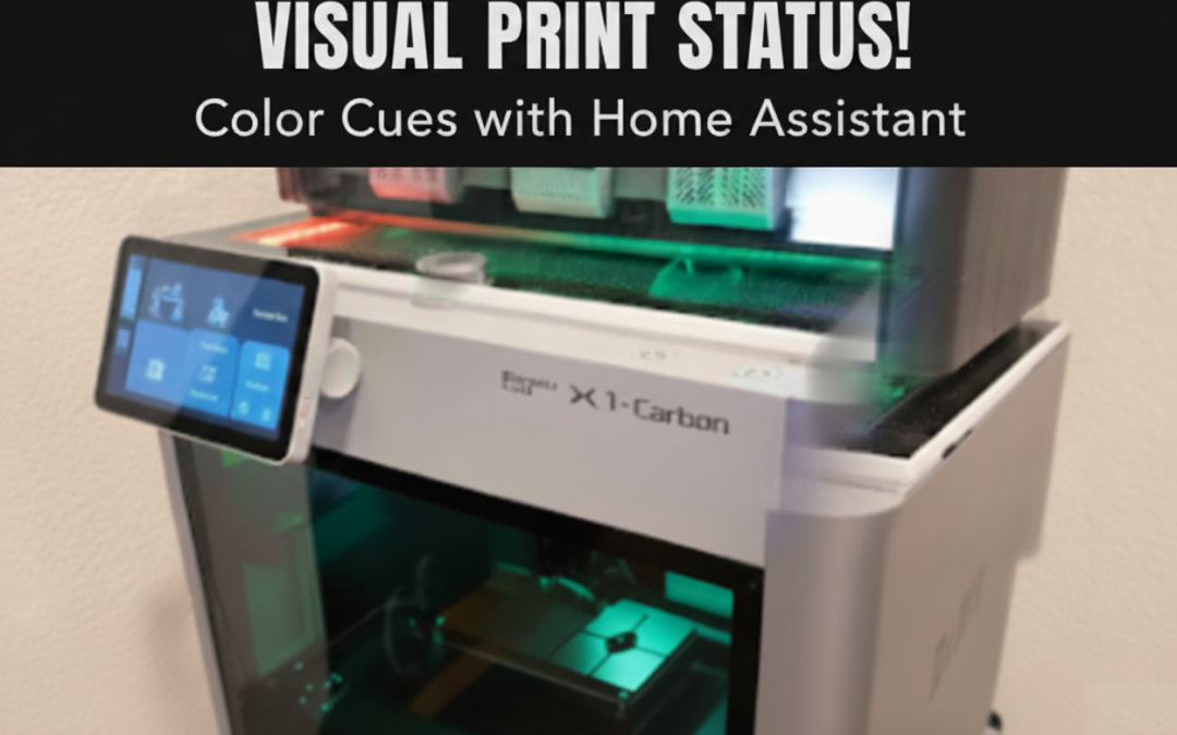
Many people are using 3D printed modifications for adding LED lights to their Bambu X1C printer. 

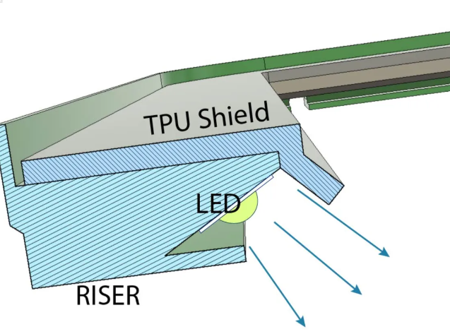
You can see the riser with a 45 degree angled LED below from the riser featured on printables. Credits to https://www.printables.com/model/365027-bambulab-top-glass-riser-4-cob-led-remix-with-led- 

This setup has a separate power supply. The normal people would simply power that on e.g. white LEDs, when they power on their 3D printer. Not was not ideal and not what most people actually want. 


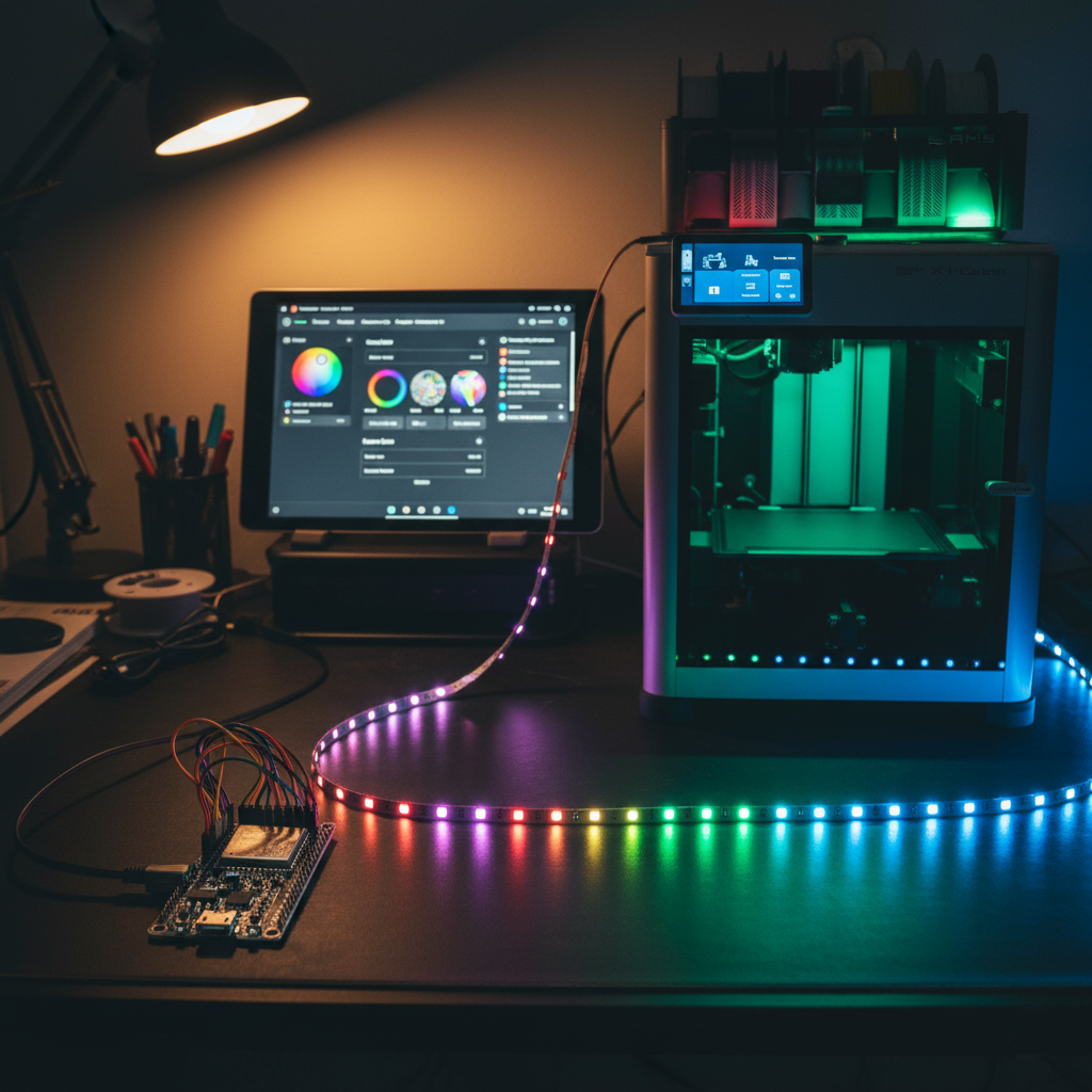
The choice to better control the lights and also add color was using an ESP32 micro controller running WLED. If you are not familiar with this, I would suggest to check it out. There are numerous postings and instructions online on how to control all kind of LED lights with ESP micro controllers or others using the WLED software.

 Check out the WLED software here https://kno.wled.ge/ and you can find all the instructions on how to create a functional LED controller. 

For my setup I used 144 LEDs / Meter for better coverage and not having to install any kind of diffuser.

The power supply will depend on what LEDs you chose as you can buy them with 5V, 12V or 24V. As a thumbnail people usually use 0.3 Watt / LED meaning if you have 144 x 0.3 = 43.2 Watt. For safety the recommendation is a 20% buffer resulting in a 50 Watt power supply for my case. Again, make your own choices depending on which LEDs, voltage and length you want. 


Using WLED to control the LEDs is great, but you want this to be automated. You can use many automations to drive light and color control. 

In my case I am using Home Assistant https://www.home-assistant.io/ and there is an integration for WLED you can install to detect and control WLED instances. 

Once you control the WLED instance of the 3D Printer lights using Home Assistant, you can automate this by installing the Bambu printer integration in Home Assistant as well. 

That integration provides you a lot of printer information, but more important status information enabling you to drive automations like this. 

As a result you can get visual cues covering the print process in white for power on or during printing by coupling the LED lights to the status of the chamber light of the Bambu X1C printer. 

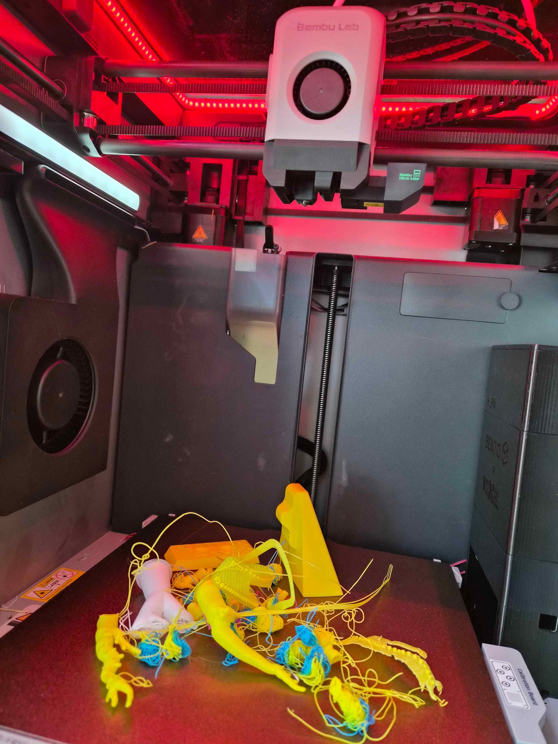
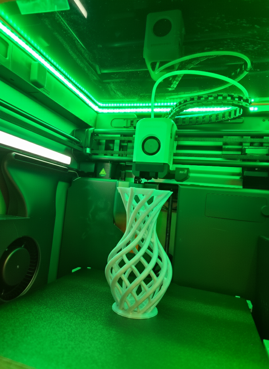
When a print failed, you can trigger the red light and after the printer finished successfully, you can enable the green light. 

You can reset the light status to white when a print starts. Of course, you can implement your own logic as I am only exposing here what is possible and what I implemented for my 3D printer setup at home.  


You can implement a single automation to drive all LED status cues, but this can become really complex really quickly.

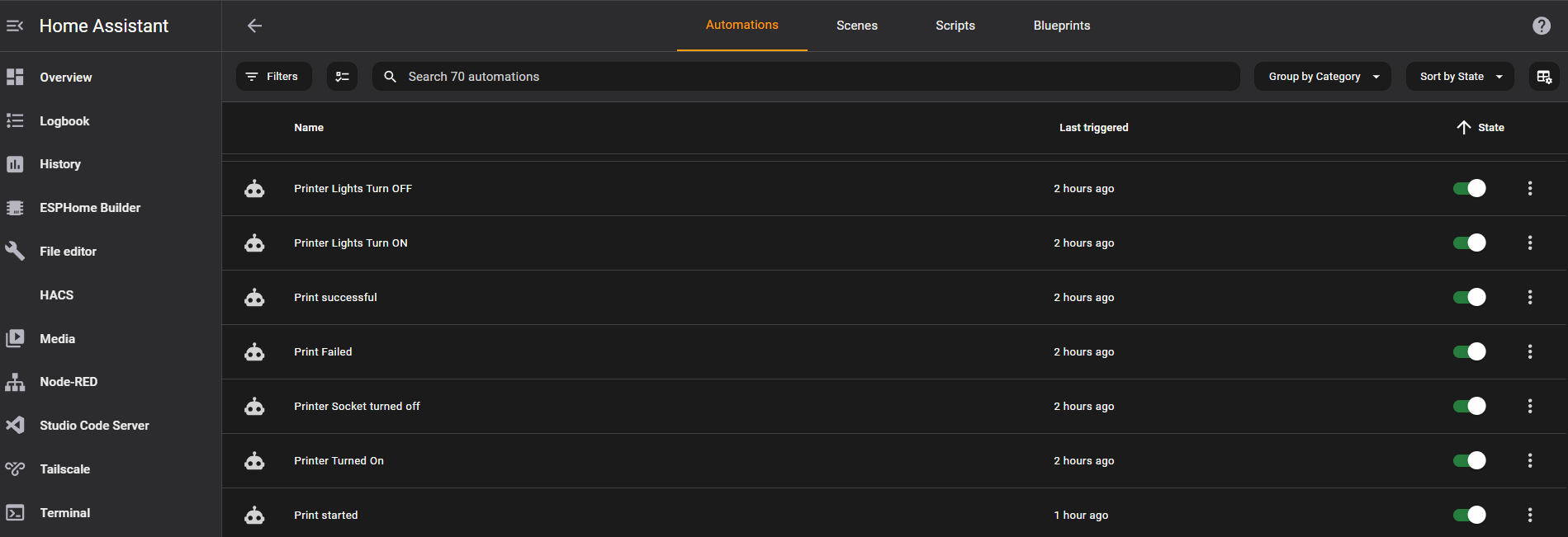
It is much easier to implement one automation for each color or cue, as you can see in the screenshot of the Home Assistant automation page. 


 Once the automations are setup, Home Assistant will drive the color cues automatically.

When you power on the printer, it starts with white based on the chamber light being turned on. 

When you start a print, it enables the white color, which is also used to reset the color after it has turned green or red. 

You can also run automations to notify your cell phone when a print is finished or failed.

Yes, you could use the Bambu lab app on your phone, but having to open the app and loggin in and then clicking on the live stream when you only want to know if it succeeded or not is overkill. 

WLED is so powerful, you could run animations as well like a specific pattern of lights in repetition or just once before turning on a specific color. The possibilities are endless here. 

You could also turn off the lights after a certain period including the chamber light if power consumption is a concern. 

You could replace the chamber light as well to match the LEDs, but that would require modifications of the existing wiring and I wanted to keep my adjustments reversable.  

In summary, you can 3D print the riser from printables, purchase an ESP32 controller and install WLED on it, purchase LED lights of your choice and make sure they fit into the riser channel.

You install the WLED and the Bambu lab printer Add-ons in Home Assistant and discover the WLED controller and call those “Printer lights”, which is also nice to be able to voice control those via voice e.g. Alexa or Google Home or Nabu from Home Assistant. 

This proejct took me two weekends once all parts arrived including printing time. 

One weekend spent on the hardware and one weekend spent on the software and integration and automation. 

I can truly say, coming down in the morning into my office and just looking at my 3D printer and seeing a green color is telling me already that it succeeded. 

Is there a chance that you could have a failed print and it shows green? Yes, but the AI of the Bambu printer is pretty good in detecting issues. 

I hope you found this helpful. Feel free to reach out with questions. Happy to answer and if you other ideas like this please share. 

Thanks. 


Motion activated LED stairs lights with voice control

Motion activated LED stairs lights with voice control

Walking up or down the stairs at night can be made to an experience by using LED lights. Being able to have different animations or LED patterns makes this even more exciting. How do you achieve such a thing?

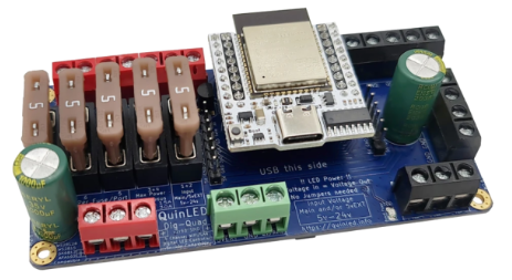
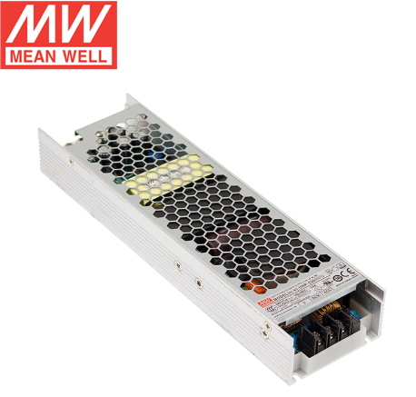
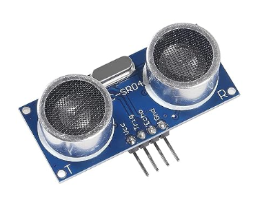
By using motion activated LED stairs lighting integrated into Alexa and Home Assistant based on Dig-Quad LED Controller using ESP32 with HC-SR04 ultrasonic distance sensors and UHP-350-12 Mean Well power supply. 

This project can be completed in many ways from just buying the components or going the extra mile and buying LED channels, diffusers and 3D printing the casings for the distance sensors. 

Let’s start with the core, which is the Dig-Quad LED controller from Dr ZZs https://www.drzzs.com/shop/ 

This controller comes with an ESP32 board already, fuses for extra protection and pre-flashed with WLED. 

You could build this yourself with an ESP32 Dev board but the ease of install and the additional protection including Youtube videos on how to install, makes this a no-brainer.


Which power supply to use will depend on the LEDs you chose e.g. 5V vs 12V vs 24V and how long and how many LED strips you want to install. There are plenty of websites and calculators out there to enable you to make the math how much WATT you need for what length and voltage. 

In my case, I went with 12V LEDs and given my length, I went with the 350W power supply. Another important aspect is the cooling method of the power supply. Having deployed various solutions like this, I can only recommend to avoid any fan based solution.

Those can be very loud and mechanical fans will fail. So the question is not if but when they will fail. This model here with the Mean Well UHP-350-12 is fanless and zero noise.

The fanless models might be a little bit more expensive but having a higher MTBF (meantime before failure) and no noise is certainly worth this price.


The type of motion sensor is important from a distance, false positive, price and reliability perspective. 

You could go overboard with mmwave doppler motion sensor like the LD2410 in which case you have to ensure the proper voltage, etc or simply go with the HC-SR04 ultrasonic sensor.

This sensor is extremely affordable and you can actually specify the distance parameters in the WLED UI to fine tune your detection radius. 

I did try the HC-SR501 motion sensor as well, but the detection reliability was not even close compared to the ultrasonic sensor, so I opted for the HC-SR04 module for the top and the bottom of the stairs.

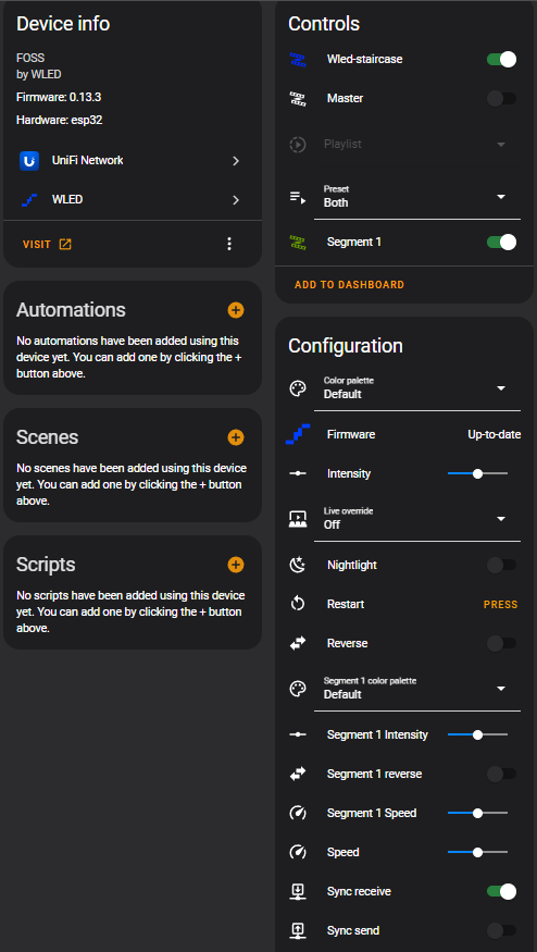
The home assistant integration is extremely easy by installing the WLED integration. Once you enable this integration it will auto-discover all your WLED instances in your home.

As you can see in this screenshot, you can conduct firmware updates, control the intensity of the lights, you can define the segments, etc. 

You could go as far as having an ESPhome Bluetooth tracker mapped to your Samsung or Apple watch and create conditions to show different patterns depending on who is going up or down the stairs. 

I opted for the stairs integration natively within WLED as this integration, while being outside of home assistant, allows you to fine tune your motion sensor parameters and set the pins for the upstairs and downstairs motion sensors via the UI. 

I should point out though, that this stairs integration is NOT natively in WLED. There are some binaries out there which include that integration or you can compile your own WLED binary with Visual Studio, which is what I did. 

Again, you don’t have to go down that route. You can simply use home assistant to do the animations for you and you could use your own motion sensors based on Zigbee or Z-wave to trigger the lights. The possibilities are endless.

Within the WLED settings in the UI, you can specify if you want that device to be discoverable by Alexa or you can use home assistant and go into the device settings and click on voice assistant and you can decide there, if you want to expose this device to Alexa and/or Google. 

A very interesting question to ask is what wins if you turn on those lights via voice and then walk up or down the stairs with the motion sensors. Will they turn off based on your timer of the motion sensors or will they stay on?

I will give you a hint… if you just use home assistant you control and decide the behavior, while using the stairs integration of WLED will do its own thing. 


Unleash your full Unify Dream machine Wifi 6 Speeds

Unleash your full Unify Dream machine Wifi 6 Speeds

With Wifi 6 and Wifi 6e and the just announced Wifi 7 standards rolling out, you want to ensure that you have the latest and greatest speeds at your home. 

There are some gotchas on the path to achieve the highest performance and I will also address the most economical vs the “Unify ONLY” method.

With the release of the Wifi 6 Access Points of Ubiquity you will notice the speed requirements of 2.5Gb/E POE to ensure the optimal performance for your network.


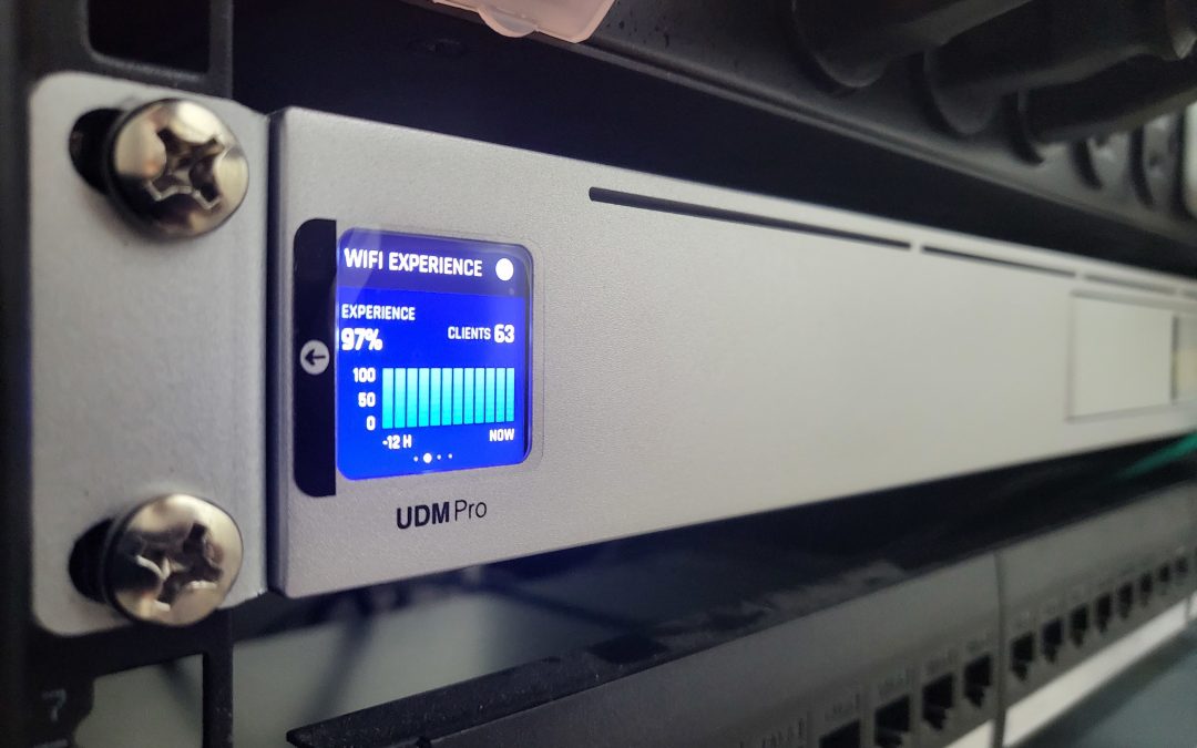
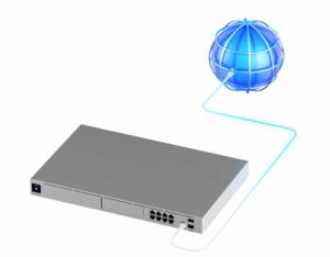
The UDM-Pro Dream Machine is a great device but if you look closely you will find 2 x 10G SFP+ ports, 1 x 1G RJ45 WAN and 8 x 1G RJ45 ports for a total of 11 ports. 

The first scenario is using the 1G RJ45 WAN port connected to your Xfinity, ATT, etc modem/router (hopefully is pass-through mode), which leaves 2 x 10G SFP+ ports to connect to your new Wifi 6 Access Points.

You would have enough ports to direct connect them to your UDM-Pro but you don’t get POE assuming you want to connect 2 Access points for redundancy reasons.


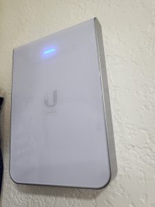
The new U6-IW Access Point, which is an In Wall Access Point powered by POE. The Access Point has additional network ports at the bottom and you will need to power this access point with POE+, if you want to have POE out.

POE+ is not required but recommended as this access point and the U6-LR (Long Range) consume about 15W on average. 

The challenge comes with the POE+ part. You have to purchase a switch with POE+, which also support 2.5Gb/E or you use the existing 10G SFP+ ports but then you need a POE injector.

You can go with the Ubiquity POE adapters or buy no-name POE adapters, but the best path of action would also be the priciest path as Ubiquity recommends their enterprise 24 Port POE+ switch for $800 all the way to their enterprise 48 Port POE+ switch for $1,600.  


With those prices for those POE+ switches the POE injectors look suddenly much more attractive than before!

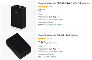
With that said, you need to be careful as not all POE injectors support the speeds you need. Some of them only support 10/100, while others support gigabit speeds which you can recognize in their part number with the G at the end.

If you go with the cheaper model like you see here on Amazon with only 10/100 saving $5, you will get a message in your Unify dashboard stating “Poor Ethernet Link Speed Try replacing your AP’s cable”. It is obviously not the cable as it is the POE injector slowing you down assuming you have the proper CAT cable for your Access Points.


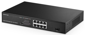
The most economical way of achieving the overall goal of best performance would be a switch. In this case an unmanaged switch which supports POE+ for 2.5Gb/E ports and has a 10G SFP+ port. There are some affordable models on Amazon and I tried 3 of them.

The first one from Yanley did not work as advertised and actually died during the install and there was no mention of that model on the manufacturer website and the manual was the wrong manual. I sent that switch back for a full refund.

The second one got delayed during shipment from China, so I ended up with the Binardata switch. 

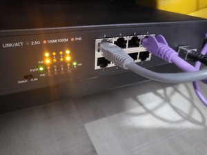
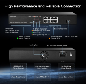
This switch comes with 8 x 2.5Gb/E ports POE+ and 1 x 10 SFP+ port. You connect this switch using a 1M SFP+ DAC cable and you connect your access points directly to the POE+ powered ports.

What nobody tells you though is that once you introduce a 3rd party switch into an ubiquity network, you will lose your ability to look at your topology map to see your Wifi clients. Given that all your Wifi clients will be connected to both or more of your access points, you will not see a single client in your topology map.

I emailed Ubiquity about that issue and their response was that 3rd party vendors incorrectly forward LLDP traffic causing this.

After emailing Binardata, they replied that this is an unmanaged switch and they don’t have a way to block LLDP forwarding. 

If you look carefully though, you will see a dip switch for VLAN support and what this dip switch does, it forces all communication from all 2.5Gb/E ports to the 10G SFP+ port blocking all communications between the 2.5Gb/E ports and this includes forwarding of all LLDP traffic. 

As a result, once you flip that dip switch your topology map will start working again and you will see your access points directly connected to your UDM-Pro and given that this is an unmanaged switch, this is totally acceptable.

Now you have a switch with 8 x 2.5Gb/E ports allowing you to connect up to 8 access points with up to 150W of total POE+ power.  


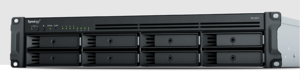
Another reason why it makes sense to use 1 of the two 10G SFP+ ports to connect to one unmanaged switch is that you most likely won’t have more than 4 x 2.5Gb/E access points in your home and given that you use the 1G port for WAN connectivity you have one more 10G SFP+ port left, which in my case talks to my Synology RS1221+ model hosting VMs, network shares, BlueIris and Home Assistant. Having one dedicated 10G ethernet connection to that device is more than appropriate. 

In summary, you can upgrade your UDM-Pro from Wifi 5 to Wifi 6 or Wifi 6e by either investing in the proper Ubiquity POE+ switch family, which will cost you at least $800 and you will get 24 POE ports while you might only need 2 or 3 of them…

or….

You purchase this affordable unmanaged switch no-name brand on Amazon Link  for $166 (and I want to make it clear that I have zero affiliation with that company and I found them on Amazon and I purchased that device at the full price).

Use the dip switch for VLAN isolating and blocking LLDP traffic giving you the ability to scale your access points with POE+ to up to 8 at a very affordable price unlocking the full speed in your home network.

I hope you found this article helpful and you will be able to break out and join the high speed highway.

New Philips Hue LED multi-color strips for a hefty new price

New Philips Hue LED multi-color strips for a hefty new price

Philips announced today a series of new products ranging from new light strips, Hue Iris, new low-cost white bulbs, etc. 

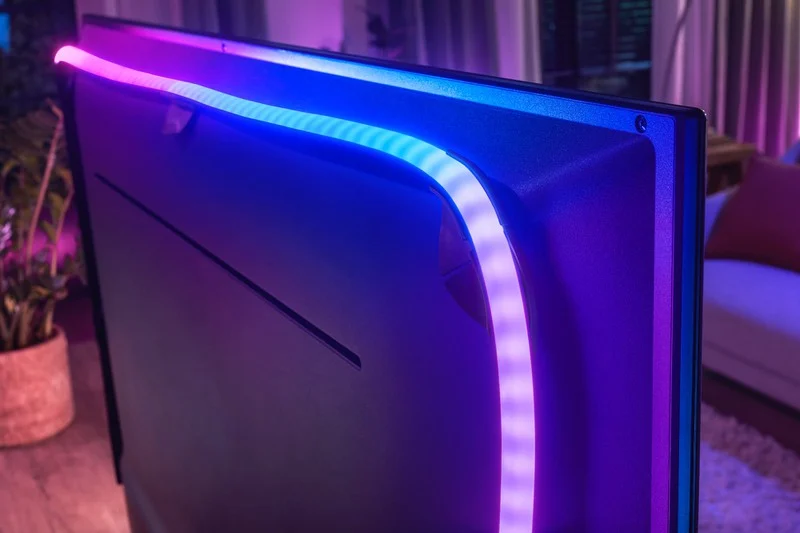
The new Philips Hue Play Gradient Lightstrip is designed to integrate seemlessly with the Philie Hue Play HDMI Sync Box. Any HDMI device will be able to be connected to the new light strip.

This new light strip comes in three lengths, as it was built with TV sets in mind and you will be able to order it in 55 inch, 65 inch and 75 inch.

The previous light strips were limited to a single color and did not support multi-color, which has now been addressed with individually addressable LEDs to provide quote “immerse home theater experience”.

You will be able to order this light strip on October 16th 2020 for a price of $199. Yes, this is correct. Philips is asking for $200 for the 55 inch version, $220 for the 65 inch and $240 for the 75 inch version. This is more than twice the price of the previous light strip version resulting in a 250% price increase. 

I would like to point out that LIFX has been offering multi-color light strips for under $100 for over 4 years now. But it doesn’t stop there. You will have to pay another $230 for the Hue Play HDMI Sync Box bringing your total price to $430. 

Let’s compare the new light strip with the cheapest version of strip you can find today on Amazon. There are hundreds of TV backlight LED products on Amazon.

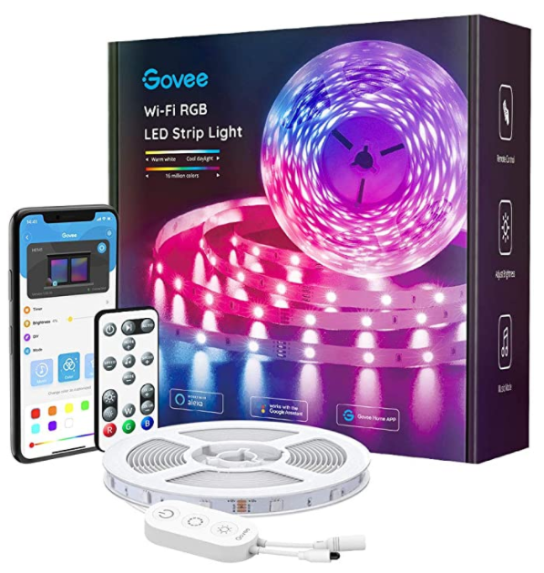
The first one I could find supporting music sync without having to use an App on your phone or a remote to run scenes and has a built-in microphone to sync with the TV sound is the one on the right. It is currently priced at $26.59. This is 6.2% of the price for the Hue Strip and HDMI sync box combined.

The lighting experience is certainly not the same as they don’t come with individual addressable LEDs, so if you care about different fading colors at the same time behind the TV, then you could invest $89,99 for the LIFX Z TV strip, which is 21% in comparison to Philips.

The downside with LIFX Z TV strip is that you will have to use an app on your phone, a raspberry PI running proxy software, or a mac pc running the proxy software to synchronize with the sound of the TV.

Granted, Philips has the most elegant solution with the HDMI sync box and no sound interference from other sources and sound sync in real-time, but that price is simply too high.

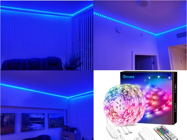
Let’s compare value. On the left side you see my installation of 64 feet 16 million colors LED strip with remote control, built-in microphone on the switch and app control on your phone. This setup will cost you on Amazon $48,59. Yes, 64 feet of LEDs for less than $50 and it works in conjunction with your TV sound as long as you have no other sound interference in the room. 

It does not offer the individual addressable LED sections to provide multi-color fading, so you can only face from one color into the other or when the sound changes the colors fade and change, but it is always one color for the strip and in different brightness depending on your sound.

 With that said, the new Philips Hue strip has certainly benefits compared to all the other options outlined here, but the price is not justified. Let’s see how the market will adopt those new LED strips from Hue. Time will tell.

Protected By
Shield Security
Verified by ExactMetrics